


![]()
![]()
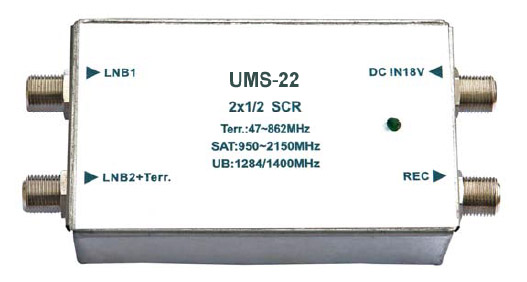
• Two satellite signal inputs which only one input with terrestrial signal, work with general multiswitch, selectable LNB (Quad) output or fixed LNB output (Quattro).
• One UnicableTM output with 2 satellite programs and terrestrial signal.
• 13/18VDC, 0/22KHz and DiSEqC (A/B) control power to each SAT input.
• All powered by external 18V/1.2A switching mode power supply.
• Maximum 2 user bands for 2 subscriber receivers.
![]()
![]()
| Typical Value | Q.C. Limit | Remark | ||
| Frequency Range |
Terrestrial (TER) | 5 ~ 862 MHz | ||
| Satellite (SAT) | 950 ~ 2150 MHz | |||
| Input Ports | LNB 1, LNB 2 + TER, DC_IN 18V | F-Type Female Connector | ||
| Output Ports | 1 Unicable O/P (2 Users) | |||
| Gain | TER | -5 dB | ≧ -6 dB | Passive |
| SAT | 5 ± 2 dB | 5 ± 3 dB | ||
| Isolation | LNB 1 / LNB 2 | 40 dB | ≧ 35 dB | |
| Return Loss | Input | 10 dB | ≧ 8 dB | |
| Output | 8 dB | ≧ 6 dB | ||
| Max. O/P Level | SAT | 93 dBμV | ≧ 90 dBμV | 35 dB IMA3 @ 50083-3 |
Traffic Indicator |
ON | Normal State | Powered by PSU & Receiver | |
| Flash | DiSEqC command received | |||
| OFF | Passive terrestrial signal working only | |||
| DC support to LNB inputs | 13/18VDC, 0/22KHz, DiSEqC (A/B) | |||
| Command from Subscriber | EN 50494 (Extension DiSEqC 1 Standard) | |||
| User Band 0 / User Band 1 | 1284 MHz / 1400 MHz | |||
| PIN Code for MDU Installation | 6F / DE | |||
| Power consumption without LNB | 85mA Max. | @ 18V Ext. PSU | ||
| External Switching Mode Power Supply | 100 ~ 240 VAC / 47 ~ 63 Hz, 18V/1.2A | Wall Mount | ||
| Dimension without PSU | 110mm (L) x 52mm (W) x 30mm (H) | |||
| Weight | 120 g | |||
| Working Temperature | -20 ~ +55 ℃ | |||
![]()
![]()
Installation Diagram for UMS-22 with LNB

Installation Diagram for UMS-22 with Multiswitch

![]()
![]()